DC Circuits

Javier 12 Feb 2019

Question

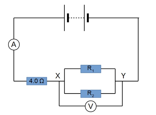
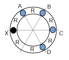
A circuit consists of three resistors, R1, R2 and R3, and two switches A and B, as shown in the figure.

Javier20190212-1.jpeg

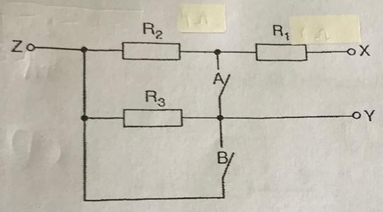
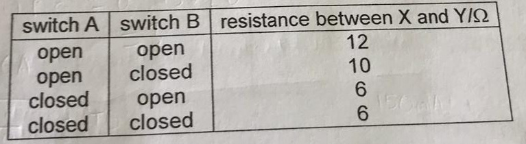
The resistances between terminals X and Y is measured for different settings of the switches A and B. The results are shown in the table.

Javier20190212-2.jpeg

a) Determine the resistance of resistors R1, R2 and R3.

b) Switch A is now closed and switch B is open. Calculate the resistance between terminals X and Z.


Answer

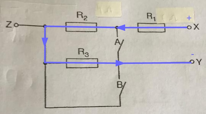
a) From the first row in the table, when switches A and B are both open, the total resistance is 12Ω.

Assuming that X is positive and Y is negative, current will flow through the circuit as shown.

Javier20190212-3.jpeg

Hence, we see that:

Javier20190212-7.jpeg

From the second row in the table, when switch A is open and B is closed, the total resistance is 10Ω.

Assuming that X is positive and Y is negative, current will flow through the circuit as shown.

Javier20190212-4.jpeg

Hence, we see that:

Javier20190212-8.jpeg

From the third row in the table, when switch A is closed and B is open, the total resistance is 6Ω.

Assuming that X is positive and Y is negative, current will flow through the circuit as shown.

Javier20190212-5.jpeg

Hence, we see that:

Javier20190212-9.jpeg

Solving the equations:
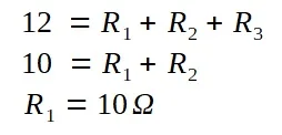
Javier20190212-10.jpeg

we obtain

R2 = 4 Ω

R3 = 2 Ω

b) When switch A is closed and B is open, we need to find the total resistance between X and Z.

Assuming that X is positive and Z is negative, current will flow through the circuit as shown.

Javier20190212-6.jpeg
Javier20190212-11.jpeg

Caitlin 9 Apr 2018

Question

Two resistors R1 and R2 are connected up in a circuit as shown in the figure below.

When the switch S is open, the ammeter reads 1.0 A and the voltmeter reads 8.0 V.

When the switch S is closed, the ammeter reads 1.5 A and the voltmeter reads 6.0 V.

Determine the values of R1 and R2. Show your working clearly.

Question.jpg

Answer

When the switch S is open, the current only flows through R2.

The circuit can be simplified as shown:

Caitiln-01.jpg

We can calculate the value of R2 directly.

Caitiln-02.jpg

When the switch S is closed, the current flows through both R1 and R2.

We can calculate the resistance across XY:

Caitiln-04.jpg

Since R1 and R2 are connected in parallel and we know the resistance across XY,

Caitiln-05.jpg

Hence, R1 is 8.0 Ω and R2 is 8.0 Ω

James 29 Sep 2016

Question

Find the potential difference across the 2.0 Ω resistor.

Find the potential difference across the open gap in the circuit.


Answer

The easiest way to find the potential difference in this case is to assign values of potential at the various points.

We first start at the sides of the cell, A and B.

We can assign any value as long as the difference between A and B is 6.0 V and A is a higher value than B.

In this case, we choose A to be 7 V and B to be 1 V.

All connecting wires are assumed to have no resistance. This means that the value of potential at all points of the same wire are of the same value.

Hence, E has a value of 7 V and C has a value of 1 V.

Since the circuit is an open circuit and no current flows, from V = I R, the potential difference across the 2.0 Ω resistor is zero.

This means that the values of the potential at both sides of the resistor are the same.

From the diagram, we can see that the difference between the potential at C and D is 0 V.

Hence, the potential difference across the 2.0 Ω resistor is zero.

From the diagram, we can see that the difference between the potential at E and D is 6 V.

Hence, the potential difference across the open gap in the circuit is 6.0 V.


Minqi 19 May 2016 - 4

Question

A set-up to control the brightness of a bulb is shown below.

X and Y are to connected to a uniform circular ring which has a constant cross-sectional area and resistivity X is connected to the left side of the ring.

Where should Y be connected for the light to be the dimmest?


Answer

The circular ring and its connection point can be seen as a connection of 6 resistors of resistance R as shown below:

When Y is connected to A, the connection is as shown below:

The effective resistance is 0.833 R.

When Y is connected to B, the connection is as shown below:

The effective resistance is 1.33 R.

When Y is connected to C, the connection is as shown below:

The effective resistance is 1.5 R.

When Y is connected to D, the connection is as shown below:

The effective resistance is 1.33 R.

Hence, connecting Y to C will result in the greatest resistance and the light bulb will be the dimmest.